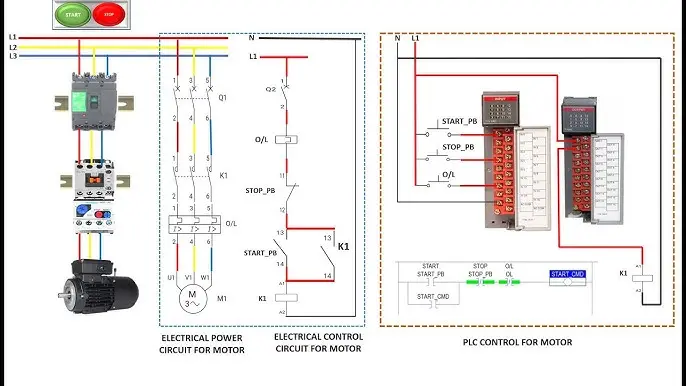
Introduction
Electrical wiring diagrams are essential tools used in residential, commercial, and industrial electrical systems. Whether you are an electrician, homeowner, engineering student, or DIY enthusiast, understanding electrical wiring diagrams can help you work more safely and efficiently. These diagrams provide a visual representation of electrical circuits, showing how components are connected and how electricity flows throughout a system.
For beginners, electrical wiring diagrams may appear complicated due to the various symbols, lines, and technical terms involved. However, once you understand the basic principles and symbols, reading and creating wiring diagrams becomes much easier. A wiring diagram serves as a roadmap that guides installation, troubleshooting, maintenance, and repair tasks.
Electrical systems are present everywhere, from simple household lighting circuits to complex industrial machinery. Without wiring diagrams, identifying connections and understanding circuit functionality would be extremely difficult. These diagrams help reduce mistakes, improve safety, and save valuable time during electrical work.
In this comprehensive guide, you will learn everything about electrical wiring diagrams, including their definition, importance, types, symbols, benefits, risks, common mistakes, and practical applications. By the end of this article, you will have a solid understanding of how wiring diagrams work and how to use them effectively in real-world situations.
What is an Electrical Wiring Diagram?
An electrical wiring diagram is a graphical illustration that shows the connections between electrical components within a circuit. It uses standardized symbols and lines to represent wires, switches, outlets, lights, motors, breakers, and other electrical devices. The primary purpose of a wiring diagram is to clearly demonstrate how electrical components are connected and interact with one another.
Unlike photographs or physical layouts, wiring diagrams focus on electrical relationships rather than physical appearance. They simplify complex systems into understandable visual representations. Electricians, technicians, engineers, and maintenance professionals rely on these diagrams to install, troubleshoot, and repair electrical systems accurately.
A wiring diagram may represent a simple household light switch circuit or a highly sophisticated industrial control system. Regardless of complexity, the fundamental goal remains the same: providing clear instructions for electrical connections.
Electrical wiring diagrams are commonly used during construction projects, equipment manufacturing, building maintenance, and electrical inspections. Understanding these diagrams is a foundational skill for anyone working with electricity.
Why is an Electrical Wiring Diagram Important?
Electrical wiring diagrams play a critical role in ensuring safe and effective electrical installations. They provide detailed information about circuit connections and help professionals understand system functionality before beginning any work.
One of the most important benefits of wiring diagrams is safety. Incorrect wiring can result in electrical shocks, fires, equipment damage, or system failures. A wiring diagram helps prevent these issues by providing a clear blueprint for correct installation and maintenance procedures.
Another significant advantage is troubleshooting efficiency. When electrical problems occur, technicians can use wiring diagrams to identify faulty components, broken connections, or wiring errors. This reduces downtime and minimizes repair costs.
Wiring diagrams also support communication among electricians, engineers, contractors, and inspectors. Everyone involved in a project can reference the same diagram to ensure consistency and accuracy throughout installation and maintenance processes.
Furthermore, electrical wiring diagrams improve planning and documentation. Future repairs, upgrades, and modifications become easier when accurate diagrams are available. They serve as permanent records of system design and configuration.
Detailed Step-by-Step Guide
Step 1: Understand the Purpose of the Wiring Diagram
Before reading any electrical wiring diagram, determine its purpose. Some diagrams are designed for installation, while others focus on troubleshooting or maintenance. Understanding the intended use helps you interpret the information correctly.
Review the title, description, and legend provided with the diagram. These details often explain the system's function and identify the components represented within the drawing.
Step 2: Learn Common Electrical Symbols
Electrical wiring diagrams use standardized symbols to represent components. Learning these symbols is essential for understanding circuit layouts.
Common symbols include:
- Light bulb
- Switch
- Circuit breaker
- Fuse
- Electrical outlet
- Ground connection
- Motor
- Transformer
- Battery
- Relay
Most diagrams include a legend or key that explains the symbols used. Familiarizing yourself with these symbols will significantly improve your ability to read diagrams accurately.
Step 3: Identify Power Sources
Locate the power source within the wiring diagram. This could be a battery, electrical panel, generator, transformer, or utility supply.
The power source is typically positioned at the beginning of the circuit. Understanding where electricity originates helps you follow current flow throughout the system.
Pay close attention to voltage ratings and power specifications. These details are critical for proper installation and troubleshooting.
Step 4: Follow Circuit Paths
Trace the lines connecting various components. These lines represent electrical conductors or wires.
Start from the power source and follow the circuit path to each component. Observe how electricity travels through switches, loads, and protective devices before returning to the source.
Understanding circuit flow helps identify how the system operates under normal conditions.
Step 5: Examine Switches and Control Devices
Switches, relays, and control devices regulate electrical flow within a circuit.
Identify:
- Single-pole switches
- Double-pole switches
- Push buttons
- Relays
- Contactors
- Timers
Understanding the function of these devices helps you determine how equipment is controlled and operated.
Step 6: Study Protective Components
Protective devices safeguard electrical systems from damage.
Common protective components include:
- Fuses
- Circuit breakers
- Ground fault interrupters
- Surge protectors
These devices disconnect power during faults, overloads, or short circuits. Their location within the diagram provides important information about system protection.
Step 7: Analyze Grounding Connections
Grounding is a critical safety feature in electrical systems.
Locate ground symbols and verify grounding paths. Proper grounding protects users from electrical shocks and reduces equipment damage during faults.
Ground connections are usually represented using standardized earth symbols within wiring diagrams.
Step 8: Verify Wire Labels and Colors
Many wiring diagrams include wire numbers, labels, and color codes.
Common wire colors include:
- Black: Hot wire
- White: Neutral wire
- Green: Ground wire
- Red: Secondary hot wire
- Blue: Control wiring
Always verify color standards according to local electrical codes because conventions may vary between regions.
Step 9: Compare Diagram with Physical Installation
After understanding the wiring diagram, compare it with the actual installation.
Check:
- Component locations
- Wire routing
- Terminal connections
- Protective devices
This step helps confirm that the physical system matches the documented design.
Step 10: Use the Diagram for Troubleshooting
When problems occur, wiring diagrams become valuable diagnostic tools.
Follow the circuit systematically to identify:
- Open circuits
- Short circuits
- Faulty switches
- Damaged wires
- Failed components
Using the diagram during troubleshooting reduces guesswork and improves repair accuracy.
Benefits of Electrical Wiring Diagrams
Electrical wiring diagrams offer numerous advantages for professionals and beginners alike.
- Improve electrical safety
- Reduce installation errors
- Simplify troubleshooting processes
- Enhance communication among technicians
- Provide clear system documentation
- Support future maintenance activities
- Save time during repairs
- Improve project planning
- Increase installation accuracy
- Help meet regulatory requirements
- Reduce equipment damage risks
- Improve understanding of electrical systems
- Facilitate training and education
- Assist during inspections
- Support system upgrades and modifications
Disadvantages / Risks
Despite their usefulness, electrical wiring diagrams also present certain challenges and risks.
- Misinterpreting symbols can cause wiring mistakes
- Outdated diagrams may not reflect actual installations
- Missing information can create confusion
- Complex industrial diagrams may be difficult for beginners
- Incorrect diagrams can lead to equipment damage
- Failure to follow diagrams properly may create safety hazards
- Poor documentation can increase troubleshooting time
- Overreliance on diagrams without physical verification can cause errors
- Inaccurate labeling may result in incorrect connections
- Electrical work always carries shock and fire risks
Common Mistakes to Avoid
One common mistake is ignoring the legend or symbol key. Every diagram may contain unique symbols or notations. Failing to understand them can result in incorrect interpretations and wiring errors.
Another frequent error is assuming wire colors are always identical across different systems. While color standards exist, variations may occur depending on location, application, and installation age. Always verify wires using proper testing equipment.
Many beginners also overlook grounding connections. Grounding plays a crucial role in electrical safety and equipment protection. Missing or incorrect grounding can create dangerous conditions.
Skipping circuit tracing is another major mistake. Instead of following the entire circuit path, some individuals focus only on individual components. This often leads to misunderstandings about system operation and troubleshooting difficulties.
Working on energized circuits without disconnecting power is perhaps the most dangerous mistake. Always turn off power, verify isolation, and follow safety procedures before performing electrical work.
Finally, failing to update diagrams after modifications can create future maintenance problems. Always revise documentation whenever system changes are made.
FAQs
1. What is the main purpose of an electrical wiring diagram?
The main purpose of an electrical wiring diagram is to visually represent electrical connections and circuit relationships. It helps users understand how components are connected and how electricity flows through a system.
2. Who uses electrical wiring diagrams?
Electrical wiring diagrams are used by electricians, engineers, technicians, contractors, maintenance personnel, inspectors, and students. They are valuable tools for installation, troubleshooting, repair, and documentation.
3. Are wiring diagrams and schematic diagrams the same?
No. A wiring diagram emphasizes physical connections and wire routing, while a schematic diagram focuses on circuit functionality using symbolic representations. Both are useful but serve different purposes.
4. Why are electrical symbols important in wiring diagrams?
Electrical symbols provide a standardized method for representing components. They simplify complex circuits and enable professionals worldwide to understand diagrams consistently.
5. Can beginners learn to read electrical wiring diagrams?
Yes. With practice and knowledge of basic electrical symbols, circuit principles, and wiring conventions, beginners can learn to read and understand wiring diagrams effectively.
6. How can wiring diagrams improve safety?
Wiring diagrams help ensure proper electrical connections, identify grounding paths, and prevent installation mistakes. This reduces the risk of electrical shocks, fires, and equipment damage.
7. What should I do before working on an electrical circuit?
Always disconnect power, verify voltage absence using appropriate testing equipment, wear protective gear, and review the wiring diagram before starting any electrical work.
8. How often should wiring diagrams be updated?
Wiring diagrams should be updated whenever modifications, repairs, upgrades, or changes are made to the electrical system. Accurate documentation improves future maintenance and troubleshooting.
Expert Tips & Bonus Points
Experienced electricians recommend studying electrical symbols thoroughly before attempting to read complex wiring diagrams. Symbol recognition is the foundation of diagram interpretation.
Always keep a copy of the wiring diagram available during installation and troubleshooting activities. Having immediate access to accurate documentation saves time and reduces mistakes.
Use colored markers or digital highlighting tools to trace circuit paths. This technique helps beginners understand current flow and identify connections more easily.
Develop a habit of tracing circuits from the power source to the load and back again. This systematic approach improves comprehension and diagnostic accuracy.
Verify wiring diagrams against actual installations whenever possible. Field modifications may differ from original plans, making physical inspection an essential part of electrical work.
Learn local electrical codes and standards. Wiring practices, color codes, and safety requirements can vary by region, so compliance is critical.
Maintain organized documentation for all electrical projects. Updated diagrams simplify future maintenance, inspections, and system upgrades.
Invest in quality testing equipment such as multimeters and continuity testers. These tools complement wiring diagrams and improve troubleshooting effectiveness.
Practice reading simple circuits before moving to complex industrial systems. Gradual learning builds confidence and improves long-term understanding.
Conclusion
Electrical wiring diagrams are among the most important tools used in electrical design, installation, maintenance, and troubleshooting. They provide a clear visual representation of electrical circuits, enabling professionals and beginners to understand system connections and functionality with greater accuracy. By learning how to read wiring diagrams, individuals can improve safety, reduce mistakes, and work more efficiently with electrical systems.
For beginners, mastering wiring diagrams starts with understanding common symbols, identifying power sources, tracing circuit paths, and recognizing protective devices. As experience grows, interpreting more advanced diagrams becomes increasingly manageable. These diagrams not only simplify installations but also serve as invaluable references for troubleshooting and future maintenance.
Although wiring diagrams can initially appear complex, consistent practice and proper training make them easier to understand. Following safety procedures, verifying connections, and keeping documentation updated are essential habits that contribute to successful electrical work.
Whether you are installing a simple lighting circuit, repairing household wiring, or studying electrical engineering concepts, the ability to read and interpret electrical wiring diagrams is a valuable skill. With the knowledge gained from this guide, you can approach electrical systems with greater confidence, accuracy, and safety while building a strong foundation for future learning and practical applications.